A multimeter is a measuring instrument used to measure current, voltage and resistance. You can read more about the relation between these under [LINK to resistors]. We will go through three useful examples of when to use the multimeter.
The multimeter consists of a display where you read data, a knob to select whether you’re checking resistance or voltage etc. and two cables used to touch the parts you want to check. The black cables should by convention always be plugged into the slot marked “COM” as in common. In all three examples below the red cable should be plugged into the slot marked “V” as in voltage.
Continuity
We test continuity, that is if current is flowing through a circuit, to make sure that a wire you are using is intact or e.g. that your circuits aren’t short wired anywhere.
Materials

- 1 Multimeter
- 1 Jumper wire
Instructions
- Turn the knob to the sound icon.
- Take the two cables and touch their ends together. You will hear a beep while they are touching. This means that there is a closed circuit.
- Take a jumper wire and the two multimeter cables. Touch one side of the wire with the tip of the black cable and the other side with the tip of the red cable. If there’s no beep, the wire isn’t intact.
If you’ve soldered a circuit together but it isn’t working for some reason, this is a good way to start troubleshooting. By checking all the soldered connections you can make sure that the circuit is closed where it should be and that there aren’t any connections where there shouldn’t.
Resistance
If you can’t remember the color code of the resistors by heart you can measure the resistance with the multimeter.
Materials
- 1 Multimeter
- 1 Resistor of optional resistance
Instructions
- Turn the multimeter knob to the side marked with the Ohm sign. You can start of with turning it to the lowest value which is 200 ohm. That value means that we can measure resistance up to 200 ohm.
- Touch each side of the resistor with the tip of a cable. The display will probably say “0.L”. This means that the resistance of your resistor is greater than what you’ve set the multimeter to check.
- Turn the knob to the next level, until you can read a number on the display. If the knob is set to “20k” and the display says “10.0” this means that the resistance is 10k ohm.
Voltage
In this example we will show you how to measure the voltage across a potentiometer. The potentiometer we use ranges from 0V to 5V.
Materials
- 1 Multimeter
- 1 Arduino Uno
- 1 Basic education shield
- 1 Potentiometer
- 2 Jumper wires
Instructions
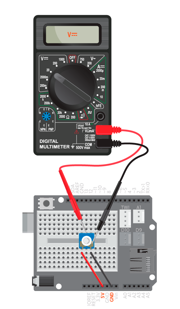
- Connect the potentiometer to GND and 5V on the on shield breadboard.
- Connect the board to the computer.
- Turn the multimeter knob to “20” on the “V” DC side. This means we can measure voltage up to 20 V.
- Touch the ground pin of the potentiometer with the black multimeter cable and the middle potentiometer pin with the red multimeter cable.
- Turn the potentiometer to see how the voltage changes.