During the programming introduction, we learned how to make small programs and animations using the computer. We were turning on and off pixels on the computer screen. As you know, the Arduino board has no screen, but it has an LED – a small lamp that can easily be turned on and off using a program. You could say that the Arduino board comes with a one ‘pixel’ screen.
That onboard LED is connected to digital pin 13. As you can see on the board, all the pins are numbered and grouped by functionality. There is a group of 14 pins (numbered 0 to 13) that are the digital and another group of 6 pins (labelled A0 to A5) that are the analog. We will explain the analog pins later on, so let’s just focus on the digital ones.
Using simple commands, we’ll control the on-board LED. This first example is what we call Blink, which will repeatedly turn an LED on and off.
In the same way that Processing programs always need to have a setup() and a draw() functions, Arduino programs need to have a setup() and a loop() ones:
setup(): this part of the program runs only once at the beginning. Here you will configure functions of the pins on the board, whether they are inputs or outputs, or if they are going to be running a more complex function like sending signals through the USB cableloop(): this part will run over and over again forever (or until you disconnect the power source). The commands in the loop are executed in order, top-down. When reaching the last command, it will restart from the beginning.
The most basic Blink program goes as follows:
void setup() {
   pinMode(13, OUTPUT);
}

void loop() {
   digitalWrite(13, HIGH);
   delay(1000);
   digitalWrite(13, LOW);
   delay(1000);
}
There you see three different commands:
pinMode(pinNumber, INPUT | OUTPUT | INPUT_PULLUP): this is used to determine whether a digital pin on the Arduino board is writing to(OUTPUT)or reading signals from(INPUT | INPUT_PULLUP)the environment.digitalWrite(pinNumber, HIGH | LOW): used to make a specific digital pin write 5 Volts (HIGH) or 0 Volts (LOW) to an output.delay(time): stops the program for a certain amount of time. Time is expressed in milliseconds. If you want your program to stop for 2 seconds you should writedelay(2000).
Also you have to remember that, as we saw during the Processing week:
- Every line ends with a semicolon ‘;’.
- Blocks of code are contained between curly brackets ‘{ }’.
- Functions start with a definition like
void. - Functions have parameters contained between brackets ‘( )’.
But going back to what that program is doing, it turns on the LED marked with ‘L’ on the Arduino board, waits for 1 second (1000 ms), turns it off, and waits for another 1 second. Then this is repeated again and again. Upload it to the board using the second button on the toolbar and see how it works.
Experiment Further
- You should now try to see what happens when you change the time inside the delay functions. If you make the delays smaller, what will happen then? Will the light blink faster or slower?
- You can also use the light to simulate a heartbeat. Check your heartbeat by measuring your pulse. You will notice that you always get two pulses, something like tha-thump … pause … tha-thump … pause … Can you simulate that rhythm with an LED? (HINT: you can copy and paste code).
- Finally, what happens when the delay becomes really small? Let’s say that you change it
delay(10).Can you still see the light blink?
Add Your Own LEDs
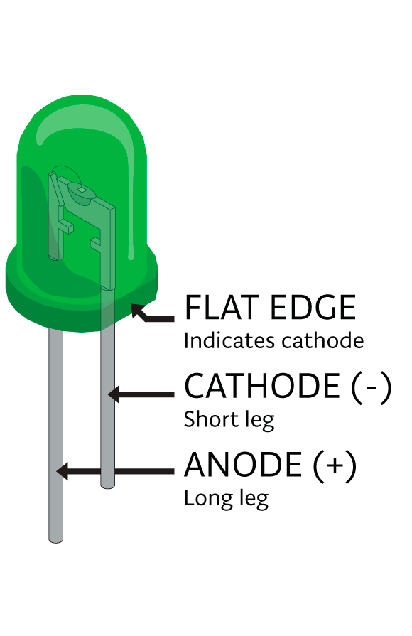
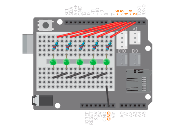
Do you want to add your own LEDs to the circuit? When working with an LED you need to remember that they have a polarity. LEDs are constructed to remind you of this. The long pin (the anode) is the positive one. When wiring it in a circuit, this is the pin that should be the connected to the positive end of power. The short pin (the cathode) should be connected to ground (0 Volts). Don’t worry if you accidentally connect them incorrectly – they will not break, but they will not light up.
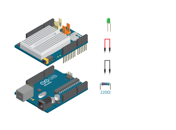
While you may not harm an LED by reversing the polarities, you can however burn them out. LEDs cannot carry a lot of current through them so in order to protect them, you need to put a resistor in front of them. The value of that resistor varies depending on the component, but in this case we will use 220 Ohm resistors with the LEDs.
To make a circuit with an LED we will use the Basic Education Shield with an attached breadboard. When mounted on your Arduino, the shield extends the board’s functionality as well adding few extra features. Read more about the breadboard here, and about the Basic Education Shield here.
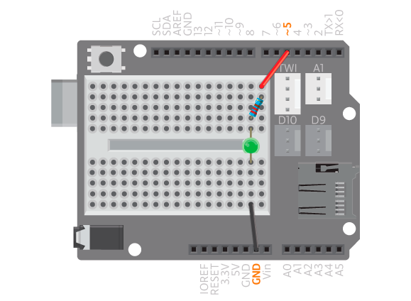
If you make the circuit shown above, you will need to change the ‘Blink’ program to address pin number 8 instead of pin number 13. The program is as follows:
void setup() {
   pinMode(5, OUTPUT);
}

void loop() {
   digitalWrite(5, HIGH);
   delay(1000);
   digitalWrite(5, LOW);
   delay(1000);
}
You could also use variables to contain the number of the pin so that it will be easier to change the program if needed.
Just to remind you, variables are locations inside the computer’s memory where we can store numbers, characters or even full strings. Variables have a type (like int for number or String for a word) and a name that you can choose to be anything.
We will use a variable to store the number that represents the pin. By writing the program this way, you only have to replace the pin number at one location instead of three. This makes it easier to make changes. Let’s see how this will look like:
int ledPin = 5;

void setup() {
   pinMode(ledPin, OUTPUT);
}

void loop() {
   digitalWrite(ledPin, HIGH);
   delay(1000);
   digitalWrite(ledPin, LOW);
  delay(1000);
}
ledPin is a variable. In this case, the possible values are 0 to 13 which are of the digital pins on the Arduino board.
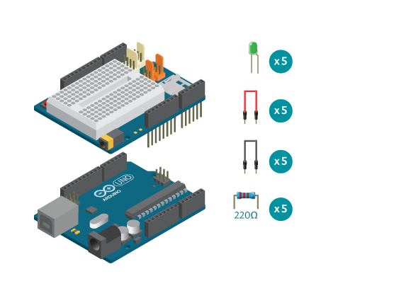
Of course, it is possible to connect and control more than one LED. In this week’s projects you will see that by connecting several LEDs, you can make what is called a VU-meter – a line of individually controlled LEDs. There are a few pre-written functions that we’ve made for you to make it simpler to use the VU-meter. Read more about the VU-meter here.
Note: We recommend that you do not use pins 0 or 1 in your projects unless you really need them. Those pins are used by the Arduino to send information the the computer. If you connect anything to them, the Arduino won’t be able to communicate with the computer or other devices using serial communication.