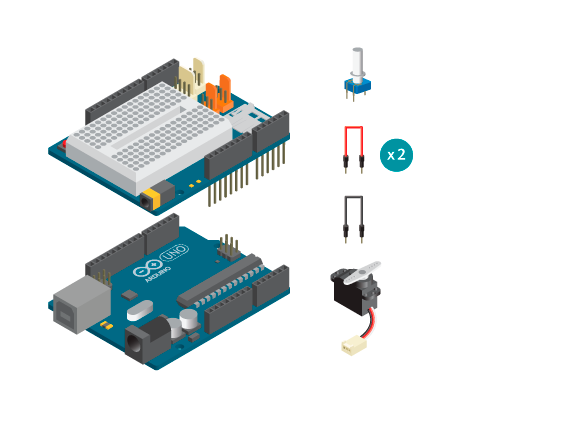
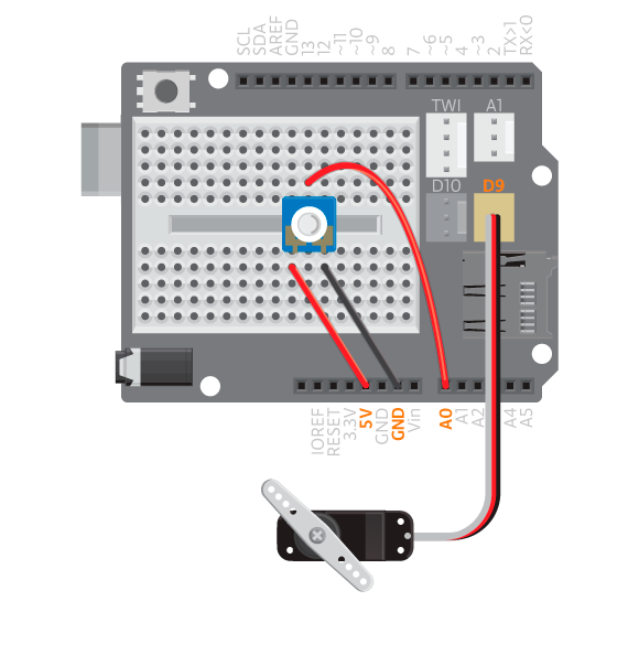
Let’s try to use an input component to control the servo. In this example we will use a potentiometer. Connect the middle pin of a potentiometer to analog input A0. Connect one of the other pins to 5V and the final pin to Ground. Connect a standard rotation servo to D9.
Upload the following code to your Arduino board:
#include <Servo.h>

Servo myservo;

int potPin = A0;
int val;

void setup() {
myservo.attach(9);
}

void loop() {
val = analogRead(potPin);
val = map(val, 0, 1023, 0, 179);
myservo.write(val);
delay(15);
}
To this example we’ve added:
- Two variables:
potpinis the pin number for the potentiometer andvalis used for the read value from the potentiometer. - In
loop()we start off with reading the value from the potentiometer. - The values we read from the potentiometer are from 0 to 1023 but we need values from 0 to 180 to control the servo. Therefore we need to use the following function:
map(value, fromLow, fromHigh, toLow, toHigh)is used to adjust the values to the range that can be used with the servo. This means that if we read 1023 in the potentiometer we’ll get 180, if we read 511, which is half the value, we’ll get 90, etc. - We then use the variable (
val) to set the position of the servo. - We use a small
delayto give the servo time to get into position.
Experiment Further
- Switch the standard servo with a continuous. Use the same code but delete the
delayfunction. Upload it and try it again. Do you thihk the different servos will act differently? If so, how and why? Think about why thedelayfunction is needed when controlling the standard rotation servo but not with the continuous rotation servo. - What other components can you use to control the servos and what can you attach to the servos to make it more fun?