The IR Array consists of 3 IR (Infra Red) sensors. If you look closely you see that each sensor has two “dots”, one blue and one black. The blue one is an IR LED and the black one is the actual IR sensor. When connected to power the IR LED emits infra red light. You can’t see it with your own eyes but if you have a camera in your mobile phone you can direct it towards the LED and on the mobile screen you will see the IR light very clearly.
When you hold the sensors close to a white surface, the white surface will reflect a lot of the IR light emitted by the LED which will be detected by the IR sensor. If you hold it over a black surface, instead almost no light will be reflected. This is why we can distinguish the black from the white.
Materials
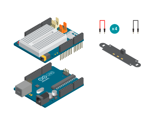
- 1 Arduino Uno board
- 1 Basic Education Shield
- 1 IR Array
- 5 jumper wires
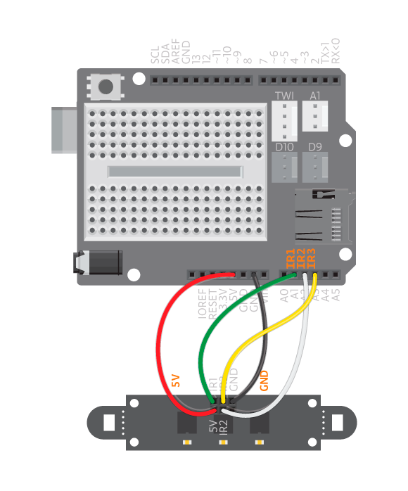
Instructions
- Connect IR1 to A1, IR2 to A2 and IR3 to A3. Connect the IR Array to GND and 5V according to the illustration.
Code
You can find the code in File -> Examples -> BasicEducationShield-> Help-> IRArray
Upload the code and open the serial monitor. Each sensor value is printed here. When you hold the IR Array over a white surface all sensors should give you a value of 400. When held over a black surface it should go down to around 330. Make sure that you’ve connected all sensor pins right by alternate each sensor between black and white and see the that values of the corresponding IR sensor is changing. E.g. if you move IR1 from black to white but only the value of IR2 is changed you need to either change the analog pins in the code or change the connections to the analog pins on the Arduino.