Resistor is a kind of electronic component that can be used to limit the current in a circuit. It also shares voltage from the power source. This is a very basic thing to know, if you want to learn about electronics, or even if you want to become a rocket scientist.
We can think of a circuit as a garden hose, which it resembles. Voltage is like the tap, you can twist the tap to adjust the pressure of water source. Current is like the amount of water flowing through the hose. You can adjust it by squeezing the hose, the harder you squeeze, the less water comes out of the hose. How hard you squeeze is equivalent to resistance in a circuit.
The unit of voltage, current and resistance is volt(v), ampere(A) ohm respectively. You can calculate the current in a circuit with this formula:
![]()
Where “I” is the current, “V” is the total voltage, and “R” is the total resistance. So if the circuit has 5v on it, and 1000Ohm (1kOhm) in total resistance, the current will be 0.005A(5mA).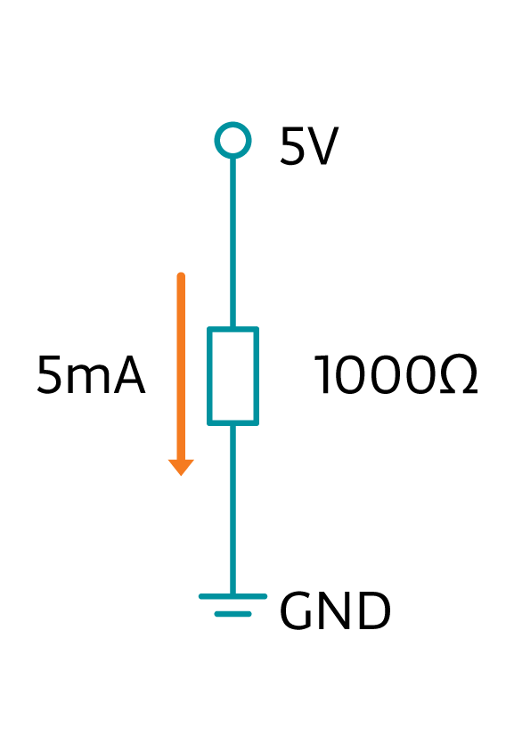
How do you know the resistance of a resistor? If you don’t have the original package, the color strips on them tell the numbers. Check this table to understand the color coding.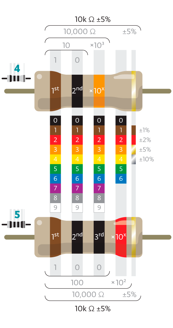
When we connect the LEDs to a Arduino board, there’s typically a 220 Ohm resistor in serial connection. The resistor limits the current, so there won’t be too much of it flowing through the LED and destroying it. At the meanwhile it also limits the brightness of the LED.
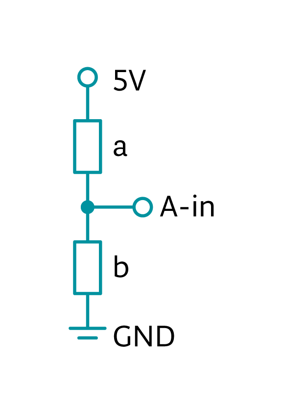
When there are multiple resistors in a circuit, they share voltages. Remember how we get analog signals? Take the example of potentiometer. One end is connected to 5v, the other end to GND, and the middle pin is connected to an analog in pin. The potentiometer works like 2 changeable resistors, their resistance adds up to a constant: Ra+Rb=Rtotal. In this case they share a total voltage of 5v, and they share it proportional to their respective resistance. You can use this formula to calculate the voltages:
![]()
Where Va is the voltage shared by a, V is total voltage, Ra and Rb are resistance of resistor a and b.
So for example if we have two resistors that are 400 ohm and 600 ohm respectively, and 5v at the power source. From the formula we know that they take a voltage of 2v and 3v each.
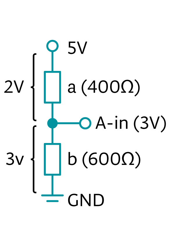
As we know, analog pins get a value between 0 and 1023 by measuring the voltage at a certain point. How to get the voltage at a point? Let’s continue with the last example. The power source has 5v, resistor a takes 2v, so at A-in it is 3v. Resistor 2 takes 3v from A-in, leaving 0v at GND, which is how it should be. We know that 5v corresponds to 1023 in analog value, so here we should get around 614 in reading.
What are the applications of this? Check out the project “Sequencer”. In this project we try to get a few distinctive analog readings, so the resistors are picked to maximize the differences. Go ahead and do some calculations, with the schematics below and resistor values provided. Compare them to the analog values in the sketch, you see a connection? How would you add more sequences? Hint: you need to add resistors of different resistances, and it’s always good idea to calculate ahead of time.